
Automatic Hydraulic Shaft Straightening Machine
A closed-loop hydraulic straightening press built for high-volume shaft production. Multi-point laser measurement, real-time deflection correction, and automatic loading/unloading combine to deliver ±0.005mm repeatable positioning accuracy with cycle times as fast as 30 seconds per workpiece. Designed for axle shafts, transmission shafts, motor rotors, and precision spindles across automotive, aerospace, and heavy machinery manufacturing.
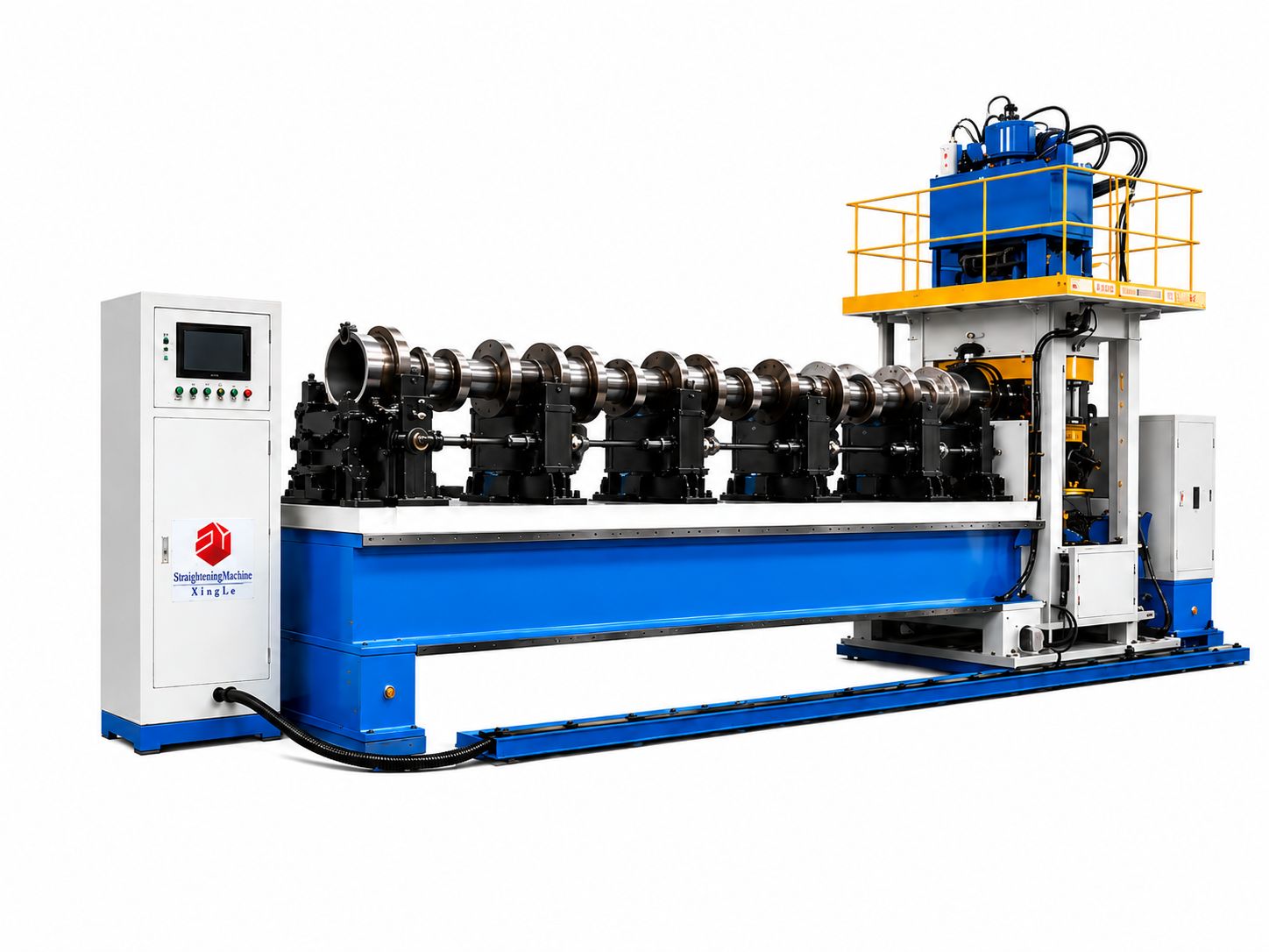
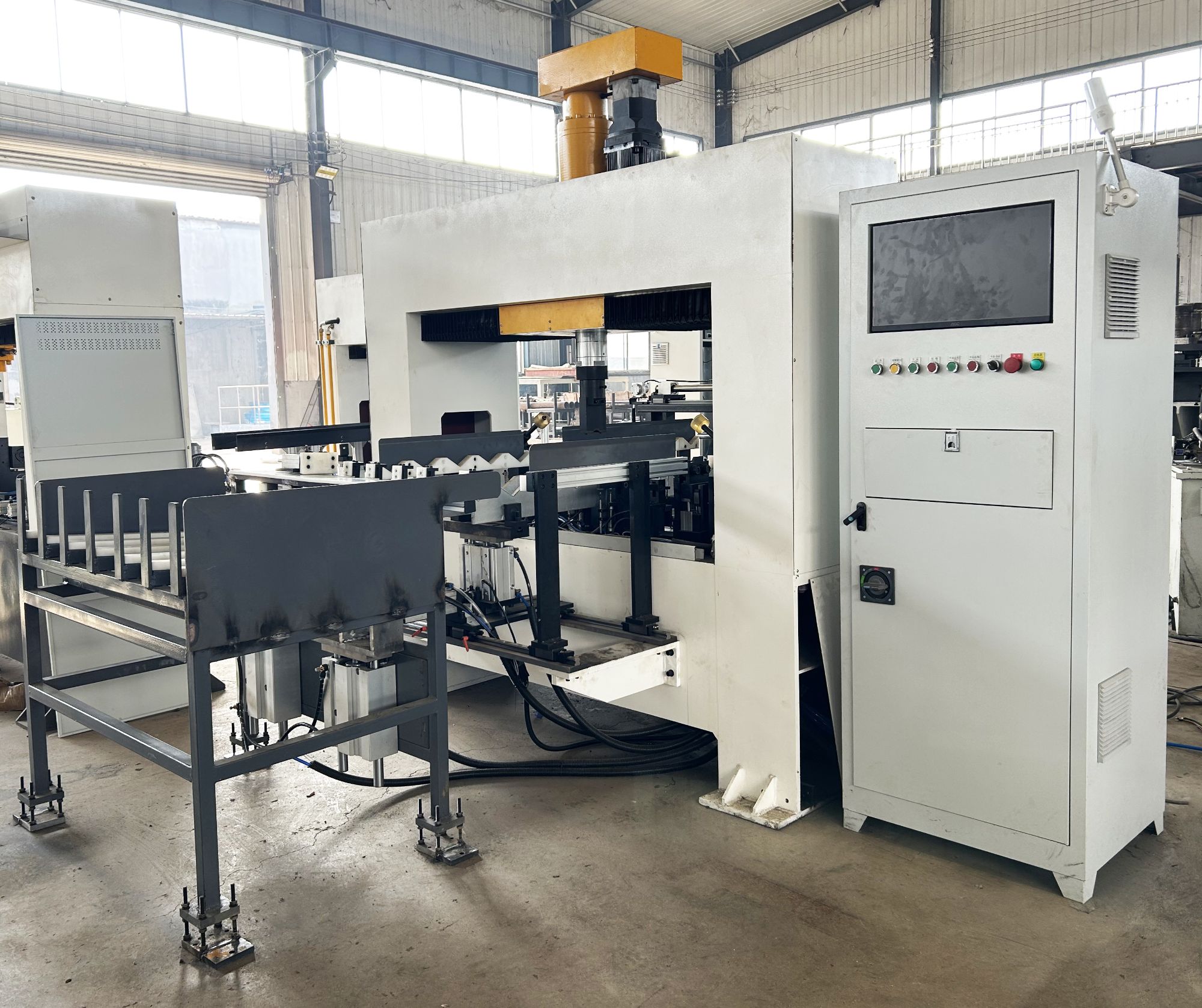
One Production Line. Over 1,000 Shafts Per Day.
Standard workpiece cycles run between 30 seconds and 2 minutes, depending on shaft length, diameter, and initial runout. That means a single production line with automatic loading and unloading consistently processes over 1,000 finished shafts per day. For high-volume metal processing and shaft manufacturing operations, this throughput replaces multiple manual straightening stations with one automated cell.
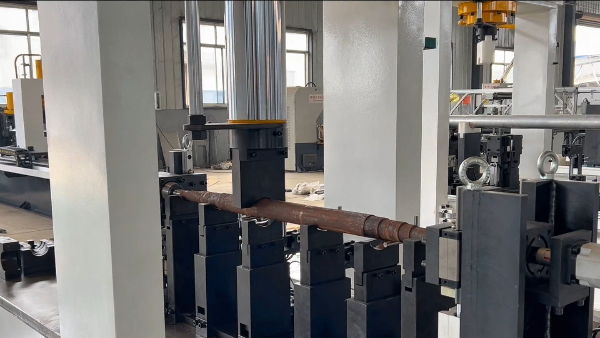
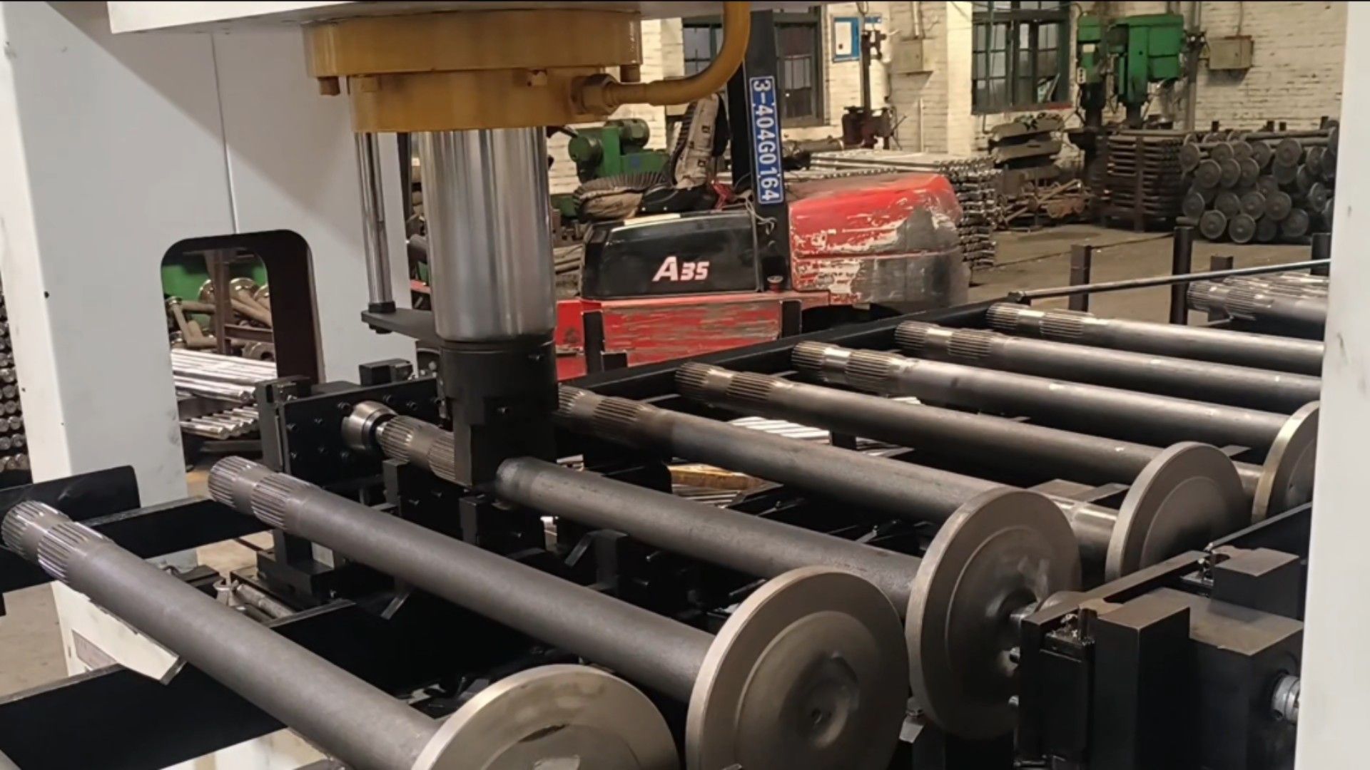
The automatic feeding system handles workpiece loading and unloading without operator intervention. Raw shafts enter on an infeed conveyor, get straightened in sequence, and exit onto an outfeed rack. Operators monitor the system, not the individual parts. Setup changeover between different shaft models typically takes under 15 minutes — adjust the V-block positions, load the part program from the touchscreen, and you're back in production.
Multi-Point Measurement. Closed-Loop Correction. No Guesswork.
Traditional manual straightening relies on operator judgment — one person's "good enough" is another person's scrap. This machine eliminates that variability. The multi-point sensor array measures deflection along the entire shaft length, the control algorithm calculates the optimal correction path, and the hydraulic ram applies precisely the force needed at exactly the right position. No trial-and-error. No spring-back surprises.
±0.005mm Repeat Positioning
Encoder-based positioning accuracy that exceeds ASME Y14.5 and ISO 2768-m tolerance bands. The measurement system recalibrates at the start of each cycle, so thermal drift during a production shift does not affect results. This is the number that matters when you're straightening electric motor rotors or high-speed spindles where runout tolerance is measured in microns.
Multi-Point Sensor Array
Not a single-point check. The system measures runout at three, five, or more positions along the shaft simultaneously. This catches compound bends and localized deflection that single-point systems miss entirely. The correction algorithm then determines which point to address first, how much force to apply, and in what sequence — something no manual operator can calculate on the fly.
Adaptive Correction Algorithm
The control software automatically adjusts correction position and hydraulic force based on real-time deflection data. For large shafts (diameters above 80mm), straightness is controllable within ±0.05mm to ±0.5mm depending on length and material. For precision shafts under 50mm diameter, the system holds ±0.02mm. Scale and oxidation on the shaft surface do not throw off the measurement — the sensors read through surface contaminants that would confuse optical-only systems.
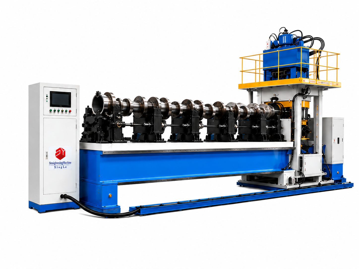
Gantry-type configuration for long shafts — extended bed length supports workpieces that exceed standard frame dimensions. Ideal for marine propeller shafts, wind turbine spindles, and heavy axles.
99% First-Pass Straightness. 95% Less Scrap.
Straightness Requirements Met
Across the full range of shaft geometries our customers run — from 20mm diameter motor shafts to 200mm industrial axles — the automatic correction cycle achieves target straightness on the first pass 99% of the time. Parts that do not meet spec on first pass are re-measured and re-corrected automatically without operator intervention.
Scrap Reduction
Manual straightening operations typically scrap 3-8% of shafts that cannot be brought into tolerance by operator effort alone — often because the operator over-corrects or misses a compound bend. Automatic correction eliminates over-correction and catches multi-axis deflection, reducing scrap losses by more than 95%. For a line producing 1,000 shafts per day, that is 30-80 fewer scrapped parts every shift.
Manual Load/Unload Required
With the automatic feeding system integrated, the machine loads raw shafts, completes the straightening cycle, and unloads finished parts without operator handling. One operator oversees the entire line rather than feeding and removing each shaft individually. This is not a labor-reduction gimmick — it is the difference between a production bottleneck and a continuous-flow manufacturing cell.
Shaft Types & Industry Applications
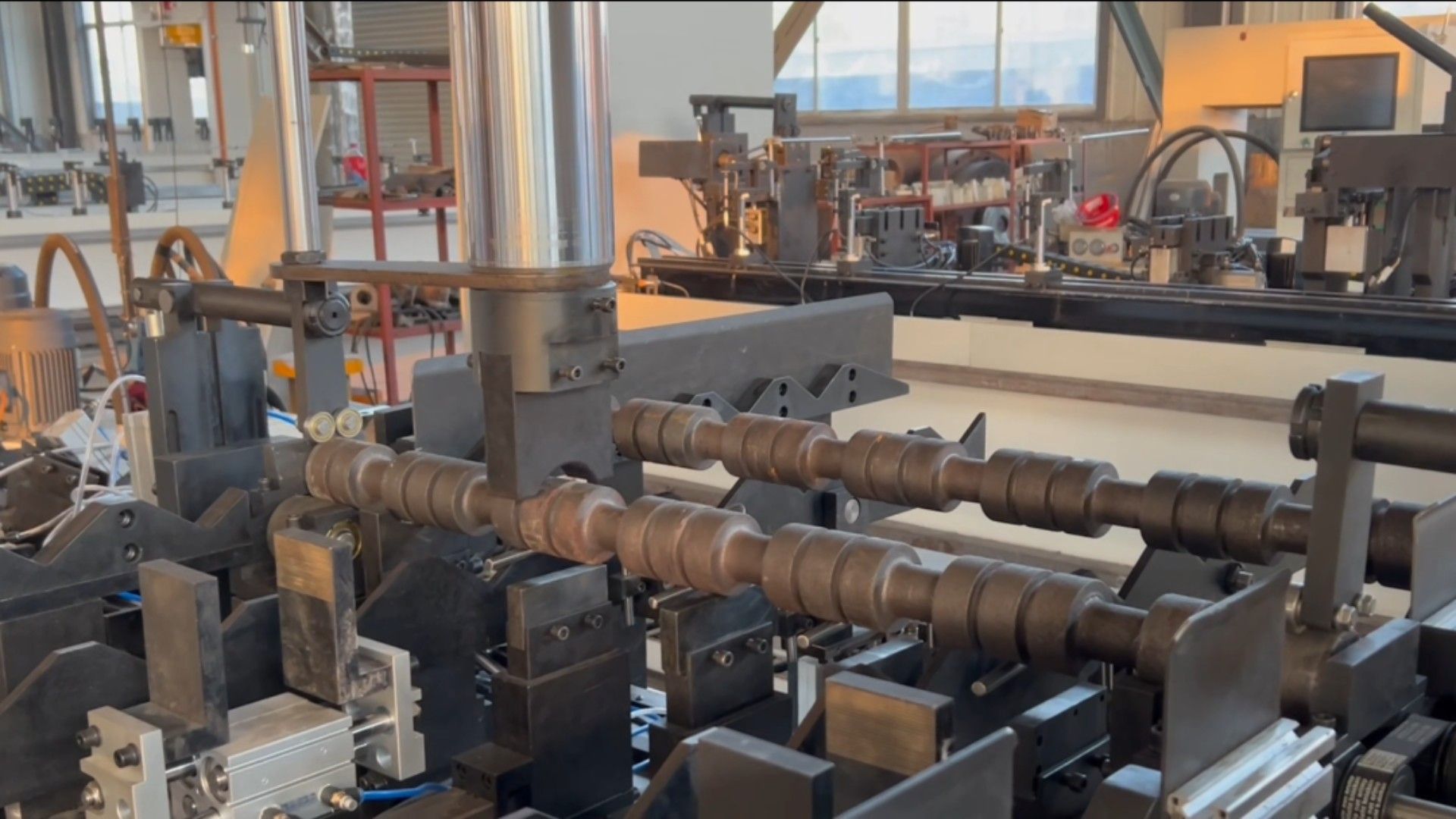
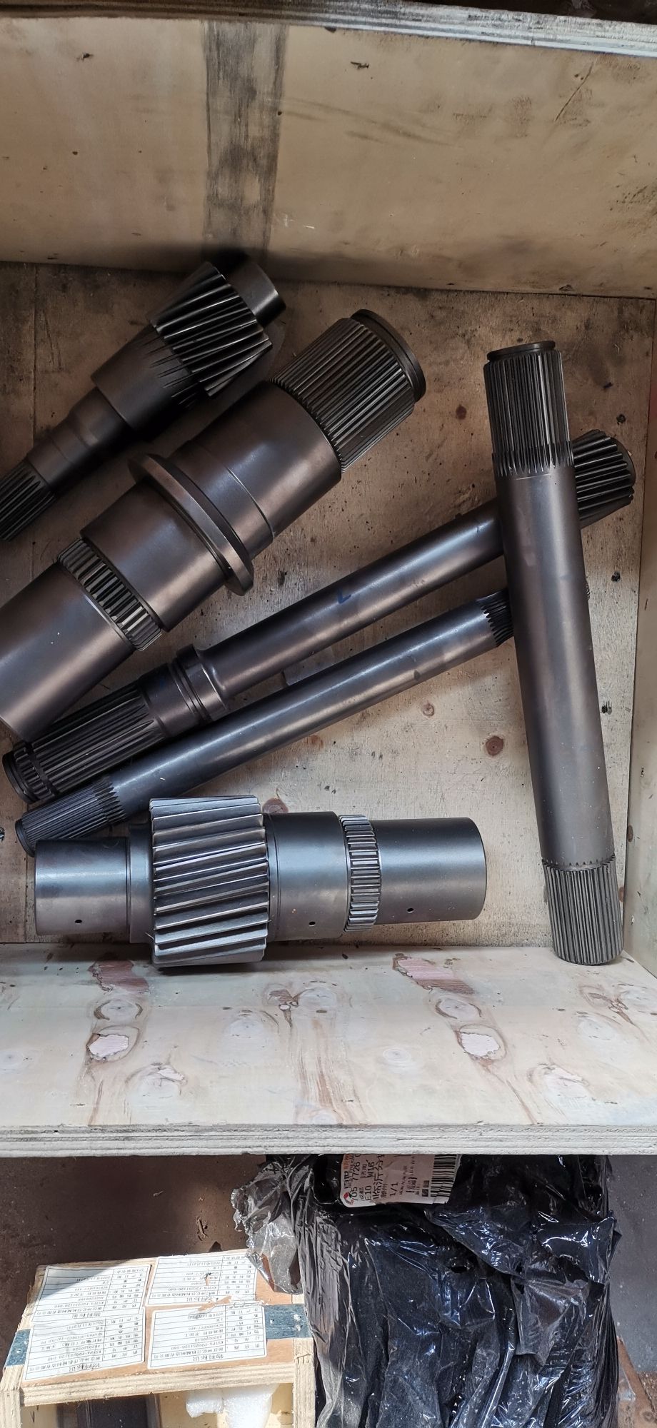
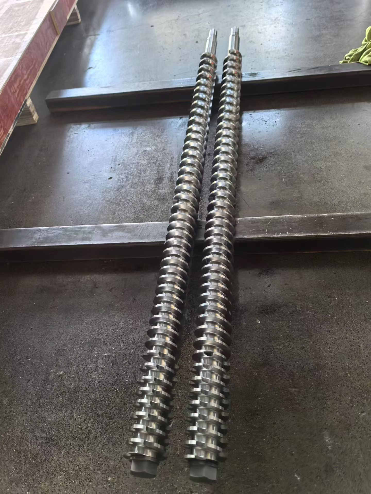
The machine handles a broad spectrum of shaft geometries. Below are workpieces that run daily on our customers' production lines. Each shaft type presents different straightening challenges — splines, keyways, diameter steps, and surface conditions all affect how force propagates through the part. The adaptive algorithm accommodates these variables without manual reprogramming.
Industries Running This Machine
Performance Data & Machine Parameters
| Parameter | Specification |
|---|---|
| Straightening Method | Servo-hydraulic, closed-loop force/displacement control |
| Measurement System | Multi-point contact/inductive sensors, real-time runout acquisition |
| Repeat Positioning Accuracy | ±0.005 mm |
| Large Shaft Straightness Range | ±0.05 mm – ±0.5 mm (dependent on length & diameter) |
| Precision Shaft Straightness Range | ±0.02 mm (shafts under 50 mm diameter) |
| Cycle Time | 30 seconds – 2 minutes per workpiece |
| Daily Output (Single Line) | 1,000+ pieces with automatic feeding |
| Control System | PLC-based with touchscreen HMI, part program storage |
| Workpiece Support | Adjustable V-blocks, accepts diameter range per customer spec |
| Feeding Options | Manual, semi-automatic roller conveyor, or full auto-loading gantry |
| Power Requirements | 380V / 50Hz 3-phase (customizable for regional standards) |
| Certifications | CE, ISO 9001:2015 quality management system |
Specifications above are standard configuration baselines. Machine dimensions, tonnage capacity, and workpiece length/diameter range are engineered to customer requirements. Contact our applications team with your shaft drawings for a configured proposal.
See This Machine Run Your Parts
Send us your shaft drawings and target straightness requirements. We run a sample test on your actual workpiece — you get measurement data, cycle time estimates, and a straightness report before you commit to anything. Or speak directly with an applications engineer who has commissioned these machines on production floors across automotive, aerospace, and heavy machinery plants.
Request a Quote
Interested in Automatic Hydraulic Shaft Straightening Machine? Fill out the form below and our team will get back to you within 24 hours.