
Почему «допустимое биение карданного вала» сложнее, чем кажется
Один контролер говорит, что вал в норме при 0,20 мм. Другой забраковывает ту же деталь при 0,25 мм. Обычно проблема не в числе. Проблема в том, что они измеряют разные вещи. «Биение» часто используют как общий термин для прямолинейности, округлости, смещения центра и торцевого биения. На карданном вале это не одни и те же дефекты, и не все они устраняются одним и тем же способом правки.
Когда мы занимаемся правкой карданных валов, первый вопрос редко звучит как «какое биение?». Он звучит так: «на что мы на самом деле смотрим?». Это различие определяет, можно ли принять деталь, отправить ее на повторную механическую обработку или исправить гидравлической правкой.
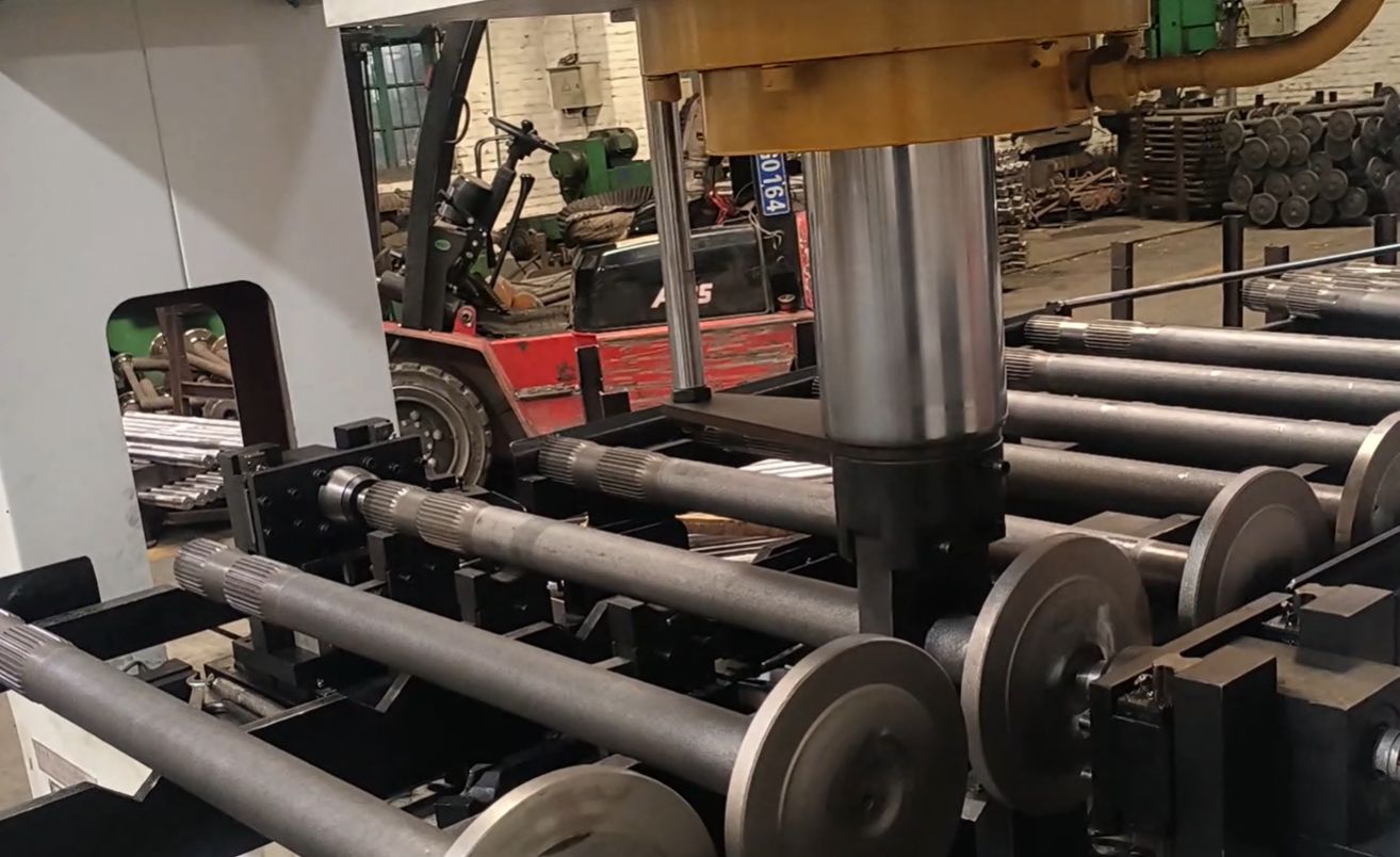
Пять дефектов, которые путают
Прямолинейность, биение, овальность, эксцентриситет и плоскостность не взаимозаменяемы. Если считать их одним и тем же, вы будете забраковывать хорошие валы или принимать плохие.
| Дефект | Что он фактически описывает | Типичная проверка | Может ли гидравлическая правка это исправить? |
|---|---|---|---|
| Прямолинейность | Отклонение оси по всей длине | Центры или призмы, индикатор по длине | Да, если это истинный изгиб |
| Биение | Перемещение поверхности относительно базовой оси при вращении | Полный размах стрелки индикатора | Только составляющую изгиба |
| Овальность | Некруглость в поперечном сечении | Двухточечный или трехточечный микрометр | Нет |
| Эксцентриситет | Смещение центра одного элемента относительно центра базы | Характер биения или проверка толщины стенки | Нет, обычно связано с механообработкой или сборкой |
| Плоскостность | Отклонение или биение торца фланца | Индикатор по торцу или поверочная плита | Нет, обычно требуется обработка торца |
Прямолинейность — самый простой случай: проведите линию через ось вала. Если эта линия искривлена, вал изогнут. Биение — другое. Биение — это то, что видит стрелочный индикатор, когда вал вращается. Идеально прямая труба с овальным сечением или смещенной от центра обработанной шейкой тоже покажет биение. Так же, как и действительно изогнутый вал. Вот почему использование биения как синонима прямолинейности создает проблемы.
Овальность часто проявляется как два скачка индикатора за оборот. Эксцентриситет обычно выглядит как один плавный цикл, как при изгибе, но он не исчезнет, когда вы правите вал. Плоскостность — в основном проблема фланца: установочная поверхность покороблена, поэтому узел бьет, даже если осевая линия вала прямая.
Измерение биения без погони за призраками
Начните с чистых поверхностей. Ржавчина, краска, окалина, сварные швы и вмятины от перемещения будут сдвигать стрелку. Если измерять по необработанной поверхности трубы, вы добавляете шум от поверхности к реальному показанию. Для карданных валов я предпочитаю сначала измерять по обработанным шейкам подшипников или центровым отверстиям. Затем при необходимости проверять тело вала отдельно, если это указано на чертеже.
Базовая установка использует центры или призмы. Медленно вращайте вручную и считывайте полный размах. TIR — это максимум минус минимум. Один цикл на оборот обычно указывает на изгиб или эксцентриситет. Два цикла указывают на овальность. Повторяющийся характер, меняющийся по осевому положению, может быть локальным перегибом или сварочной деформацией. Всегда проверяйте, что опоры чистые и соосные; изношенный центр внесет собственную погрешность.
Биение — это не прямолинейность. Изогнутый вал всегда будет показывать биение, но биение не всегда означает, что вал изогнут.
Типичные ошибки: наконечник индикатора не перпендикулярен, магнитное основание смещается, слишком большой предварительный натяг, деталь установлена не полностью, измерение через шпоночный паз или шлицы. Малое расстояние между призмами может позволить длинному валу прогибаться и изменить показание. Также не касайтесь детали достаточно долго, чтобы температура стабилизировалась. Вал, который неравномерно нагревается, может показывать отличие на несколько сотых.
Приемка — это не одно универсальное число. Для автомобильных карданных валов многие мастерские работают с TIR 0,15–0,30 мм на диаметрах под подвесной подшипник, тогда как высокоскоростные или электромобильные применения часто требуют менее 0,10 мм. Но чертеж всегда главнее. Уточните, какой элемент измеряется, на какой длине, относительно какой базы и какой допуск TIR или прямолинейности применяется.
Когда гидравлическая правка имеет смысл
Если измеренное отклонение в основном обусловлено истинным изгибом, а деталь находится в пределах корректируемого диапазона, автоматическая гидравлическая правка может быть контролируемым этапом исправления, а не игрой в угадайку. Ключевое слово — контролируемым. Вы не стучите по валу, пока он не станет выглядеть прямым. Вы измеряете точки максимума, прикладываете точечное усилие, снова измеряете и повторяете.
Это хорошо работает для сплошных валов, толстостенных труб, прутков и некоторых профилей. Тонкостенные или закаленные детали требуют большей осторожности; слишком большое локальное давление может вызвать трещины или вмятины. Здесь важны обнаружение трещин и обратная связь. На нашем оборудовании цикл правки картирует деталь, выбирает позиции нажима, прикладывает усилие и автоматически проверяет результат. Данные правки могут передаваться в MES, поэтому вы можете отследить начальное и конечное TIR каждого вала. Это превращает правку биения из догадки оператора в повторяемый процесс.
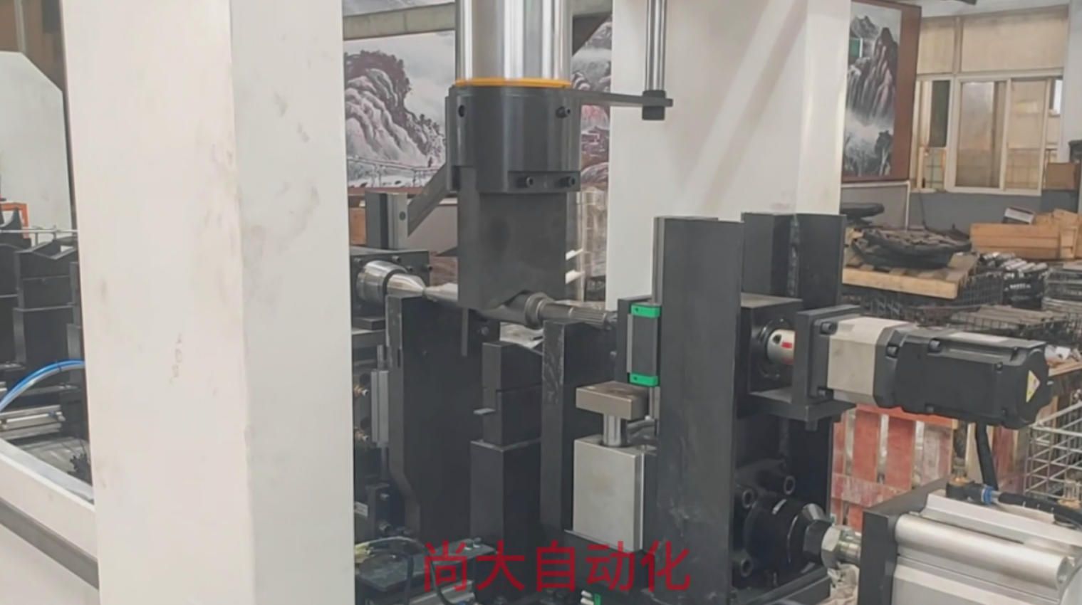
Правка точечным усилием может достигать точности около 0,01 мм на подходящих деталях, без царапин и вмятин, если оснастка и усилие подобраны правильно. Один оператор может обслуживать несколько станков, потому что система выполняет загрузку, измерение, правку и регистрацию данных. Это важно, когда нужно исправить сотни валов за смену, а не один прототип.
Но гидравлическая правка не исправляет овальность, разнотолщинность стенки, смещенную механообработку или покоробленный фланец. Если сигнал TIR в основном от овальности, вы будете давить, а стрелка почти не улучшится. Если это эксцентриситет, правка может сместить не тот элемент. Поэтому мы возвращаемся к одному и тому же: определите дефект, прежде чем выбирать способ правки.
Более четкий путь «принять или исправить»
Когда на измерительном столе появляется показание биения карданного вала, я люблю прогнать его по короткому чек-листу:
- Измерение чистое: опоры, база, положение индикатора, температура?
- Характер — один цикл, два цикла или локальный?
- Дефект — изгиб, овальность, эксцентриситет или плоскостность фланца?
- TIR превышает допуск чертежа в указанном месте?
- Если это истинный изгиб, подходит ли диапазон правки для гидравлической правки?
Если ответ указывает на реальный изгиб в пределах корректируемого диапазона, автоматическая гидравлическая правка — надежный способ вернуть вал в допуск без брака. Если данные указывают на другое, правка только потратит цикл впустую. Когда проблема неясна, мы обычно начинаем с настройки измерений. Большинство загадочного биения — это не загадочный вал, а перепутанное определение.
Если вы сталкиваетесь с проблемой пределов биения карданного вала или решаете, подходит ли правка для вашего процесса, свяжитесь с нашей командой.